
20% vs 60% Long Carbon Fiber Loading in LFT-G: A Head-to-Head Decision Guide for Structural Parts
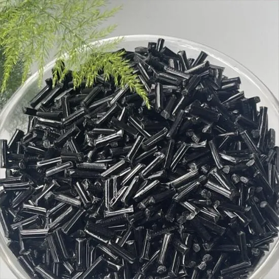
The decision in one paragraph. LFT-G long carbon fiber reinforced composite plastic is specified anywhere between 20% and 60% long carbon fiber. That window is a design range, not a menu. The published LFT-G benchmark set — 350 MPa tensile strength to ISO 527-2, 510 MPa flexural strength and 30,700 MPa flexural modulus to ISO 178, 40 kJ/m² Izod impact to GB/T 1843, 7.8% elongation at break to ISO 527-2 and 1.28 g/cm³ density — is the verified performance envelope for the material family. The loading level itself is fixed per part during material design. So the practical question for an engineer or a buyer is never “which number is better”, but “which position inside 20–60% survives my part’s load path, service envelope and acceptance test”.
The Problem: Two Failure Modes, One Datasheet That Cannot Decide For You
Structural part specifications fail in two directions, and both trace back to the same gap. Over-specify the reinforcement content and the part still has to be moulded: flow behaviour changes, fibre distribution becomes harder to control, warpage risk rises, and the ductility budget the design assumed may not be there at first-article. Under-specify it and the shortfall does not appear on the drawing — it appears later, at vibration test, at thermal cycling, or in the field after eighteen months of alternating load.
Neither error can be avoided by reading a datasheet alone, because the widely circulated LFT-G figures describe the family, not the specific loading you are about to purchase. Tensile strength, flexural strength, flexural modulus, impact energy and elongation at break are all reported against defined test standards, and those reports are generated for the material actually produced. That is the reason this guide is organised as a decision sequence rather than a property list: each step consumes a verified fact from the LFT-G specification and converts it into a question you can put to a supplier.
There is a second, commercial version of the same problem. Procurement teams are often asked to compare quotations for “the same” carbon fibre composite plastic when the two quotes sit at opposite ends of the reinforcement range. Without a shared decision framework, the comparison collapses into price alone, and the cheapest quote wins the order and loses the programme. The framework below is designed to be run before the quotation is opened, so that the technical position is fixed and the commercial comparison is apples-to-apples.
Industry Background: Why Loading Level Became a Live Question
Long fibre thermoplastics have moved from a niche composite format to a mainstream structural option. The global long fibre thermoplastics market was valued at USD 2.58 billion in 2025 and is projected to reach USD 4.06 billion by 2031, according to MarketsandMarkets. The wider carbon fibre reinforced plastic market was estimated at USD 19.27 billion in 2024 by Grand View Research. Growth of that scale is driven by applications where mass reduction is a functional requirement rather than a cosmetic one — and it is precisely those applications that force the loading-level decision.
The material itself is the reason the decision exists. Long fibre reinforced thermoplastic engineering material differs from ordinary short fibre reinforced thermoplastic in fibre length: short fibre compounds sit below 12 mm, while LFT processing produces fibre lengths of 5–25 mm. Those long fibres are impregnated with resin through a special mould system to produce fully impregnated long strips, which are then cut to the required length. The most widely used base resin is PP, followed by PA6, PA66, PPA, PA12, MXD6, PBT, PET, TPU, PPS, LCP and PEEK. Conventional reinforcements include glass fibre and carbon fibre; specialty fibres include basalt fibre and quartz fibre.
Fibre length is also why the loading decision is more sensitive here than in a short fibre compound. The reinforcement network carries load over longer distances, and the way that network forms inside the tool is influenced by how much fibre is present and how the melt flows. That interaction is why loading level, base resin and part geometry have to be decided together.
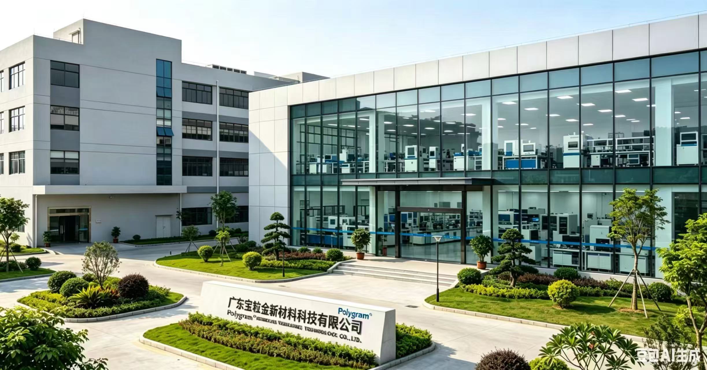
The supplier behind the LFT-G specification discussed here is Guangdong Baolijin New Material Technology Co., Ltd., which trades as Polygram. Polygram is a high-tech enterprise headquartered in Huangjiang Town, Dongguan City, Guangdong Province, specialising in the research, development, production and sale of thermoplastic carbon fibre composites (LFT), conductive and antistatic plastics, and graphene thermally conductive plastics, with 20 years of experience in the polymer composite materials industry. The company was founded in 2017, operates a 4,000 m² facility with 30 employees and an R&D team of 10 engineers, reports annual output of 12,000,000 units, and exports 30% of production to Europe and America and Southeast Asia. Its published technical scope covers material design, raw material production, precision mould development and injection moulding.
Detailed Solution: What the Verified LFT-G Data Does and Does Not Cover
Start by separating what is proven from what must be proven. The following values are the verified benchmark data for Carbon Fiber Composite Plastic in the LFT-G and LFT long carbon fibre reinforced formats:
- Density: 1.28 g/cm³.
- Tensile strength: 350 MPa, tested to ISO 527-2.
- Flexural strength: 510 MPa, tested to ISO 178.
- Flexural modulus: 30,700 MPa, tested to ISO 178.
- Elongation at break: 7.8%, tested to ISO 527-2.
- Izod impact: 40 kJ/m², tested to GB/T 1843.
- Reinforcement content: 20–60% long carbon fibre.
- Colour and form: black, supplied as long carbon fibre reinforced composite material.
- Packaging: 20–25 kg per bag, customisable.
Those figures describe the material family as published. They are the numbers you use to set the structural floor — the minimum stiffness and strength the part must retain after the loading level, gating, wall thickness and fibre orientation are all fixed. They are not a substitute for a part-specific report, and they should never be used to estimate what a 60% version of a specific moulding will do. The standards themselves set the expectation: international testing frameworks for carbon fibre properties include ISO 527-4/5 for tensile properties and ASTM D4018 for continuous filament tows, in addition to the ISO 527-2, ISO 178 and GB/T 1843 methods used on the LFT-G compound.
The service envelope is equally important, because it is what the loading decision ultimately serves. LFT carbon fibre composite plastic is designed for weight reduction of 30–50%, high rigidity and impact resistance across a temperature range of −50°C to 120°C — a range that also supports the “high temp” framing often used in electrical and automotive specifications. It is designed for long-term outdoor or in-cabin service in high-pressure environment heating cycles, and for conditions requiring chemical resistance, extended range and safety.
Mechanically, the material is expected to operate in a mode involving static load-bearing capacity plus dynamic jolting, vibration and high-frequency start-stop, and to work through 24-hour industrial-grade continuous operation with alternating loads in the air. It is designed for environments with strong wind, sand and dust, damp heat, and high fatigue cycles. Alongside structural performance, the LFT-G platform supports insulation and electromagnetic shielding behaviour, and Polygram’s wider material portfolio includes conductive and antistatic plastics and graphene thermally conductive plastics for parts where dissipation or thermal paths matter. Medical-use compliance is addressed separately: ISO 13485 compliant grades are available for medical applications.
The application list published with the LFT-G specification is deliberately narrow and specific: long carbon fibres are applied to a range of commercial and military aerospace applications, including radomes, drones, aircraft, missiles, satellites and aerospace fuel tanks. The LFT material data extends that to aerospace, military industry, new energy vehicles, low-altitude economy, robotics, semiconductors and sports equipment.
Step-by-Step: Choosing Between the 20% End and the 60% End
Run these seven steps in order. Each one produces an output that the next step consumes, and each one is anchored to a verified fact rather than an assumption.
Step 1 — Write down the load case and the service envelope
Before any material conversation, specify the part against the conditions the material is designed for: static load plus dynamic jolting and vibration, high-frequency start-stop, alternating loads in the air, and continuous operation over long duty cycles. Add the environmental set — −50°C to 120°C, damp heat, wind, sand and dust, and chemical exposure where relevant. A part that only ever sees static load and a part that sees alternating in-air load do not belong at the same point in the reinforcement window, even if the drawing dimensions are identical.
Step 2 — Set the structural floor from the published benchmarks
Take 350 MPa tensile strength (ISO 527-2), 510 MPa flexural strength and 30,700 MPa flexural modulus (ISO 178) as the verified performance level of the LFT material. Then decide how much margin your part needs after manufacturing effects. This step tells you whether the part is stiffness-driven or strength-driven, which is the single biggest influence on where it should sit in the 20–60% range.
Step 3 — Audit the toughness and ductility budget
Izod impact of 40 kJ/m² to GB/T 1843 and 7.8% elongation at break to ISO 527-2 define the ductility the material can deliver. Parts exposed to impact, drop, stone strike or thermal shock need this budget protected; parts that are purely stiffness-critical can tolerate a different balance. This is the step where over-specifying reinforcement content most often causes a surprise, because the part that passed the static calculation can fail the impact criterion.
Step 4 — Convert the structural answer into a mass answer
Against a density of 1.28 g/cm³, and a design target band of 30–50% weight reduction, check whether the loading position you are considering still delivers the mass saving the programme was sold on. The verified reference point here is a real programme: in an eight-year new energy vehicle Tier 1 ODM engagement running from 2018 to 2026, a power battery pack upper cover and protective shell produced in long carbon fibre composite delivered 42% weight loss compared with aluminium and an 18% cost reduction, while passing UL94 V0 and IP6K9K, with no after-sales cracking or leakage.
Step 5 — Lock the loading level during material design
The loading level is not selected from a shelf; it is fixed during material design, together with the base resin. Polygram’s ODM customisation covers the process of material, mould opening and injection moulding, which is the sequence in which the decision becomes real. Base resin choice (PP, PA6, PA66, PPA, PA12, MXD6, PBT, PET, TPU, PPS, LCP or PEEK) and the 20–60% long carbon fibre content are specified together, because both affect flow and the fibre network that forms in the tool.
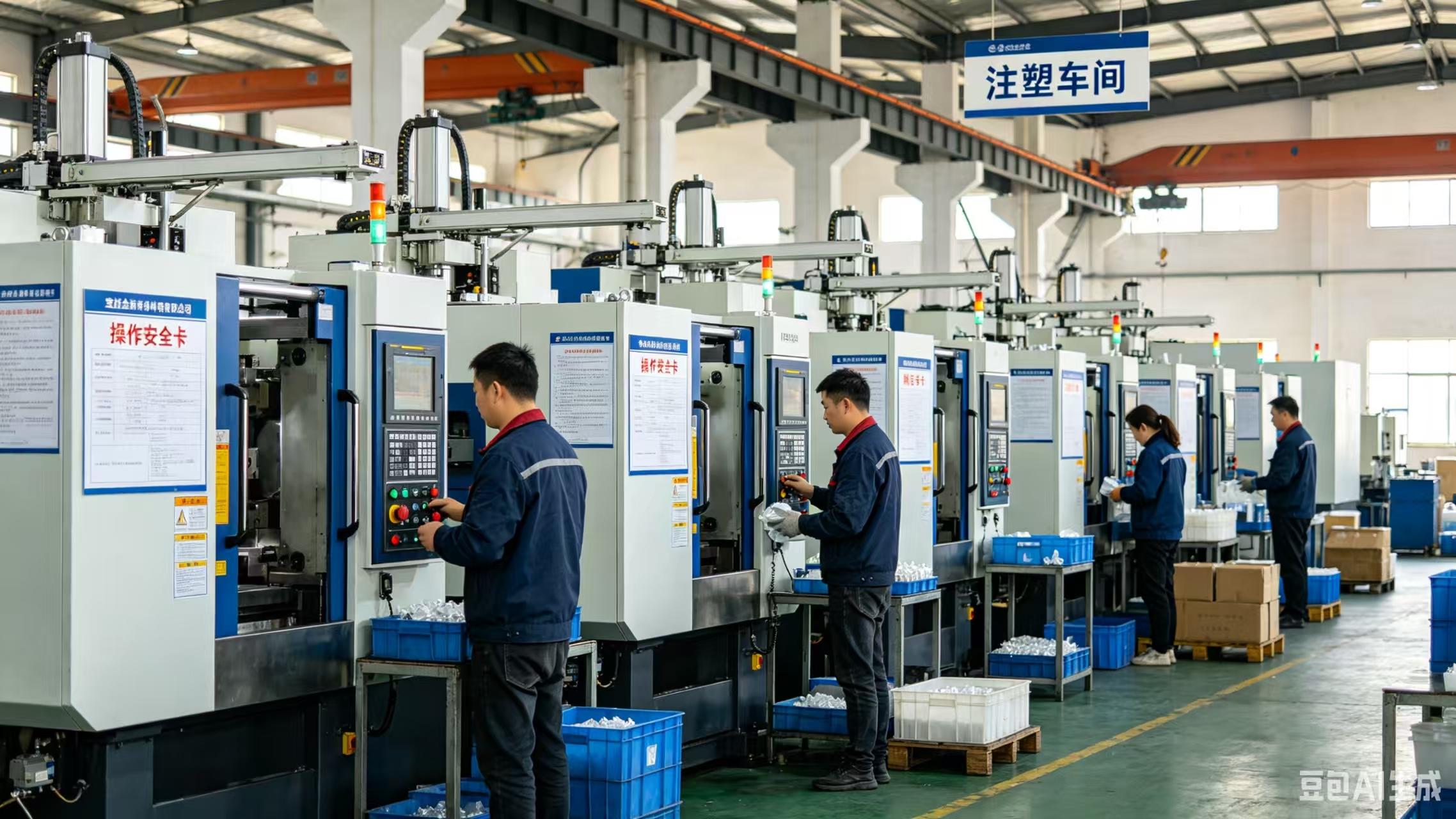
Process capability is part of the decision, not an afterthought. The published equipment set for long carbon fibre composite work includes precision injection moulding machines, wear-resistant double-alloy screws, high-gloss hard moulds rated HRC52+, high-precision mould temperature control and nitrogen-assisted injection moulding. Fibre length in the finished part is a function of all of it: LFT fibre lengths of 5–25 mm are what distinguish the format from short fibre compounds below 12 mm.
Step 6 — Prove the position on a part-specific report
Once the loading level is fixed, the specific values that matter — tensile, flexural, modulus, impact, elongation, plus the acceptance criteria of your programme — must be confirmed on test reports for the material produced. Polygram applies 100% test as its quality control standard. For a colour-sensitive assembly, note that the standard supply is black; additional packaging formats are customisable but colour specification should be confirmed in the material design stage.
Step 7 — Fix the commercial terms around the technical decision
Only after Steps 1–6 should commercial terms be negotiated. At that point the specification is stable and quotations are comparable. The published commercial parameters are: MOQ of 50 units, lead time of 30 days, monthly capacity of 12,000,000 units, packaging of 20–25 kg bags with customisable format, and remote after-sales support.
Use Cases: Where the 20% vs 60% Decision Actually Plays Out
Aerospace and defence structures
The LFT-G specification is published against commercial and military aerospace applications including radomes, drones, aircraft, missiles, satellites and aerospace fuel tanks. These are the parts where the reinforcement decision has the least room for error: radomes combine structural and electromagnetic requirements, while fuel tanks and airframe parts combine chemical resistance, fatigue resistance and mass targets. Alternating loads in the air and high fatigue cycles are the operating conditions that make ductility, not just stiffness, part of the structural case.
New energy vehicle components
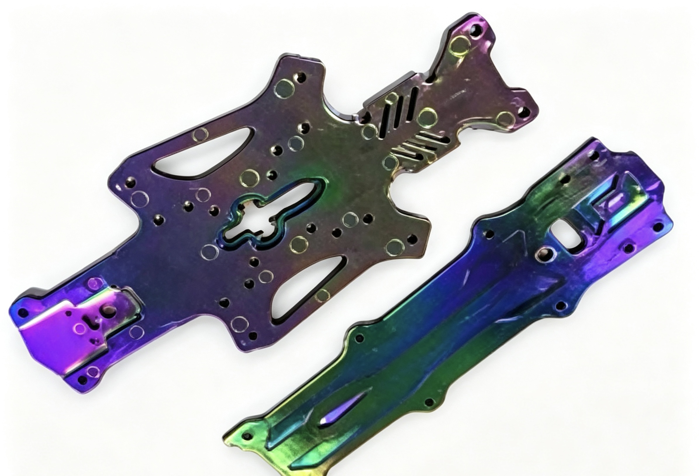
Automotive Carbon Fiber Composite Plastic demands a different balance. The verified programme reference is the battery pack upper cover and protective shell described above, where the part had to deliver high-voltage insulation, shock resistance and electrolyte resistance simultaneously. The engineering detail worth noting for the loading decision is the coefficient of thermal expansion: the composite was developed to be CTE-compatible with aluminium at 28 ppm/°C, and the long carbon fibre formulation allowed integrated injection moulding with low float fibre suitable for high-speed mass production. Volume was 120,000 units per year.
Robotics, semiconductors and electronics
Robotic structures, AGV load-bearing beams, servo motor brackets and semiconductor-adjacent parts are published application areas for this material family. Here the decision is driven by stiffness-to-mass ratio, dimensional stability and low warpage rather than peak strength. Where static dissipation or shielding is required, Polygram’s conductive and antistatic plastics and electromagnetic shielding composite plastic capabilities sit alongside the structural LFT grades, and graphene thermally conductive plastics address thermal paths. The wider electromagnetic shielding composites market reached USD 1.97 billion in 2024, with a projected CAGR of 7.1% through 2033.

Sports equipment and consumer structures
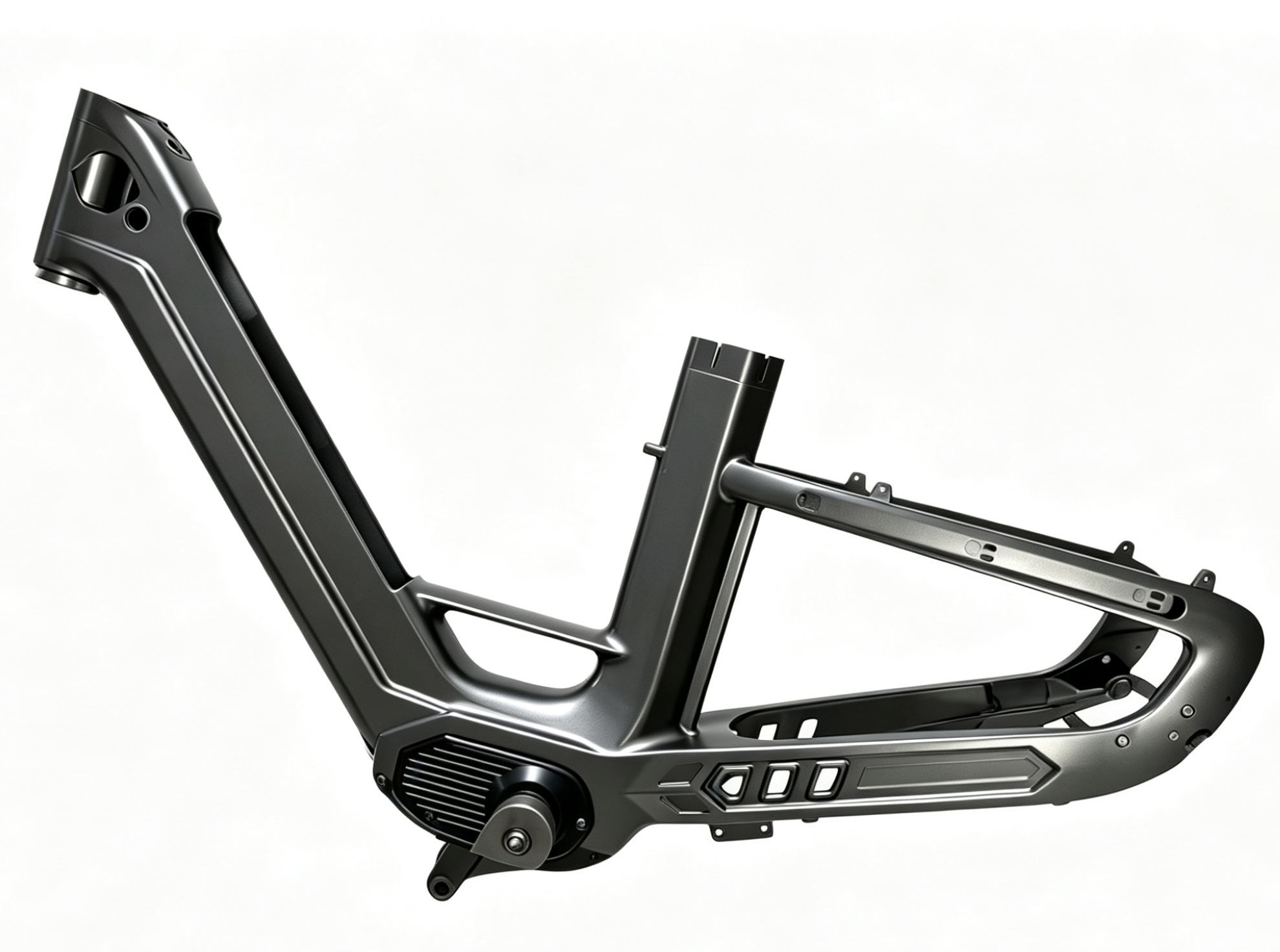
Sports equipment is a published application area for LFT carbon fibre composite plastic, and it typically rewards the toughness side of the balance: bicycle frames and similar structures see repeated impact, vibration and fatigue loading in ways that pure stiffness targets do not capture. The verified 40 kJ/m² Izod impact and 7.8% elongation at break figures are the reference points for that trade.
Low-altitude economy and medical
The low-altitude economy appears in the published industry list for LFT materials, spanning drone fuselage, arm and landing gear structures and multi-rotor centre frames. For medical applications, ISO 13485 compliant grades are available, which means the loading decision must be taken with the compliance route in view from the start rather than retrofitted at validation.
20% vs 60%: Comparison Tables
Table 1 lists what is verified for the LFT-G family and what must be confirmed per part. Table 2 is a decision-orientation aid for choosing which end of the range a part should be evaluated near; it contains no part-specific property values.
| Decision criterion | Verified LFT-G benchmark | What must be confirmed for your part |
|---|---|---|
| Tensile strength | 350 MPa to ISO 527-2 | Part-specific tensile value at the selected loading level |
| Flexural strength | 510 MPa to ISO 178 | Part-specific flexural value after gating and fibre orientation |
| Flexural modulus | 30,700 MPa to ISO 178 | Actual stiffness of the moulded geometry |
| Impact toughness | 40 kJ/m² Izod to GB/T 1843 | Impact performance at the service temperature |
| Elongation at break | 7.8% to ISO 527-2 | Ductility retained in the finished part |
| Density | 1.28 g/cm³ | Mass of the finished part against the 30–50% reduction target |
| Reinforcement window | 20–60% long carbon fibre; fibre length 5–25 mm | Exact loading level fixed in material design |
| Service envelope | −50°C to 120°C; damp heat, wind, sand and dust, high fatigue cycles | Your programme’s actual duty cycle |
| Commercial parameters | MOQ 50 units; lead time 30 days; 20–25 kg bags, customisable | Quotation against the locked specification |
| Part demand profile | Evaluate near the 20% end when… | Evaluate near the 60% end when… |
|---|---|---|
| Load path | The part is stiffness-driven and the section geometry can carry the load | The part is strength-driven and section geometry is constrained |
| Impact exposure | Drop, strike or shock loads are in the duty cycle and ductility must be protected | Impact exposure is low and mass reduction dominates the requirement |
| Geometry and flow | Long flow paths, thin walls and tight warpage limits | Thick sections and shorter flow paths with mass-critical targets |
| Thermal duty | Service temperature stays well inside the published envelope | The part runs toward the upper end of the published temperature range |
| Change control | Existing approvals depend on current impact and elongation data | The part is new and qualification can start at the higher loading level |
Read the two tables together. Table 1 fixes what is known; Table 2 shows which direction the part’s own requirements push the decision. Neither table replaces the seventh step — a part-specific test report at the selected loading level.
FAQ: 20% vs 60% Long Carbon Fiber Loading in LFT-G
Which standards should the test report for a 20–60% long carbon fibre LFT-G part reference?
For the compound itself, the LFT-G and LFT datasheet values are reported against ISO 527-2 for tensile strength and elongation at break, ISO 178 for flexural strength and flexural modulus, and GB/T 1843 for Izod impact. Broader carbon fibre testing frameworks include ISO 527-4/5 for tensile properties and ASTM D4018 for continuous filament tows. Programme-level acceptance criteria can go further: the verified new energy vehicle battery pack cover programme passed UL94 V0 and IP6K9K, and ISO 13485 compliant grades are available for medical applications. Buyers should require the report to name the standard, the loading level and the test date, because a family-level datasheet does not evidence a part-specific claim.
Can the long carbon fibre loading be adjusted for one specific structural part?
Yes, within the published 20–60% window. The loading level is fixed during material design rather than selected from a fixed catalogue, and Polygram’s ODM customisation covers the full process of material, mould opening and injection moulding. Base resin can be specified from PP, PA6, PA66, PPA, PA12, MXD6, PBT, PET, TPU, PPS, LCP and PEEK, with fibre lengths of 5–25 mm produced by the LFT process. The work is supported by an R&D team of 10 engineers, and 100% test is applied as the quality control standard. Because loading level, resin and tooling interact, the adjustment should be scoped as a material-design project rather than a simple substitution.
How should cost be assessed when moving from the 20% end to the 60% end?
No price list is published for either end of the range, so cost must be assessed through a quotation issued against a locked specification. The verified commercial reference point in this material family is a new energy vehicle Tier 1 ODM programme where long carbon fibre composite production delivered an 18% cost reduction compared with the aluminium baseline, alongside 42% weight loss. The practical purchasing rule is to specify the lowest loading level that passes the part’s acceptance tests, because reinforcement content is only one cost driver and an over-specified part also risks rework at validation. Published commercial parameters to negotiate around are an MOQ of 50 units and a lead time of 30 days.
How is a sample validated before mass production?
Validation follows the ODM sequence: material design, mould development, then injection moulding, with 100% test applied to output. Process equipment for long carbon fibre composite work includes precision injection moulding machines, wear-resistant double-alloy screws, high-gloss hard moulds rated HRC52+, high-precision mould temperature control, and nitrogen-assisted injection moulding. Samples should be evaluated against the same standards that will govern serial supply — ISO 527-2, ISO 178 and GB/T 1843 for the material properties, plus any programme-specific criteria such as UL94 V0 or IP6K9K. The MOQ for initial supply is 50 units.
What lead time and packaging format apply to LFT-G orders?
The published lead time is 30 days, supported by a monthly capacity of 12,000,000 units and annual output of 12,000,000 units at a 4,000 m² facility. Material is supplied in black, in 20–25 kg bags with a customisable packaging format. Exports account for 30% of production and serve Europe and America and Southeast Asia, with remote after-sales support. Supply continuity is demonstrated by the new energy vehicle programme that has run from 2018 to 2026 at 120,000 units per year with no after-sales cracking or leakage. To move from evaluation to a decision, request a sample or quotation and download the technical brochure — contact Polygram at baolijin@carbolft.com or via WhatsApp.
Conclusion: Decide the Position Before You Compare the Price
The 20% versus 60% question in LFT-G long carbon fibre loading is answered by the part, not by the material. The verified envelope — 350 MPa tensile to ISO 527-2, 510 MPa flexural strength and 30,700 MPa flexural modulus to ISO 178, 40 kJ/m² Izod impact to GB/T 1843, 7.8% elongation at break, 1.28 g/cm³ density, within a 20–60% reinforcement window and a −50°C to 120°C service range — sets the level the material can reach. The loading level that a specific structural part should actually use is fixed during material design, against that part’s load case, impact exposure, geometry, thermal duty and acceptance test.
Run the seven steps in order, confirm the result on a part-specific test report, and only then open the quotation. That sequence is what turns a specification argument into a purchasing decision, and it is the same sequence that keeps a programme out of the two failure modes this guide opened with.
Next step: sample, quotation or brochure
Send the part’s load case, service envelope and target mass to baolijin@carbolft.com and ask for a loading-level recommendation inside the 20–60% window, with a part-specific test plan and a quotation. You can also download the technical brochure (PDF) or visit www.carbolft.com for the full material data. Polygram — Guangdong Baolijin New Material Technology Co., Ltd. MOQ 50 units. Lead time 30 days. Packaging 20–25 kg per bag, customisable.
Have Questions or Need More Details?
Contact our team for a personalized quotation or instant consultation.
Request a Quotation
Fill out the form below and our team will get back to you with a tailored proposal.
WhatsApp Direct Chat
Prefer to chat in real-time? Message us on WhatsApp for instant assistance & quick answers.
- Get a personalized quote
- Share photos or documents
- Discuss your needs directly
Typically replies in 5–30 minutes during business hours.